 Hyundai Equus: SRS Control Module (SRSCM) Repair procedures
| 2. |
Disconnect the battery negative cable and wait for at least three minutes before beginning work. |
| 3. |
Remove the floor console assembly.
(Refer to Body - "Floor Console Assembly") |
| 4. |
Pull up the lock of the SRSCM connector to disconnect the connector (A and B). 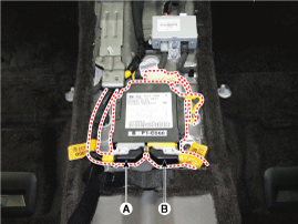
|
| 5. |
Remove the SRSCM mounting bolts (3EA) from the SRSCM, then remove the SRSCM.
|
You must remove or install the SRSCM or other SRS components with the ignition switch OFF to avoid accidental airbag deployment. |
|
| 2. |
Disconnect the battery negative cable and wait for at least three minutes before beginning work. |
| 3. |
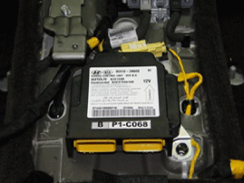
Install the SRSCM with the SRSCM mounting bolts.
Tightening torque :
7.5 ~ 10.5 N.m (0.76 ~ 1.07 kgf.m, 5.5 ~ 7.7 lb-ft)
|
| • |
Use new mounting bolts when replacing the SRSCM after a collision. |
| • |
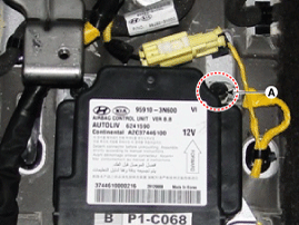
When installing the SMSCM bolt, install the ground wire (A) with a bolt as indicated in the picture. |
|
|
| 4. |
Connect the SRSCM harness connector. |
| 5. |
Install the floor console assembly.
(Refer to Body - "Floor Console Assembly") |
| 6. |
Reconnect the battery negative cable. |
| 7. |
After installing the SRSCM, confirm proper system operation:
Turn the ignition switch ON; the SRS indicator light should be turned on for about six seconds and then go off.
|
If the SRSCM is replaced always, perform variant coding. Also, perform the lateral G sensor 0 point setup.
(Refer to Brake System – “Yaw-rate and Lateral G Sensor”) |
|
After replacing the SRSCM with a new one, the “Variant Coding” procedure must be performed.
| 1. |
On SRSCM variant coding mode, the airbag warning lamp
periodically blinks (ON: 0.5sec., OFF: 0.5sec.) until the coding is
normally completed. |
| 2. |
If the variant coding fails, DTC B1762 (ACU Coding Error) will be displayed and the warning lamp will turn on.
In this case, perform the variant coding procedure again after confirming the cause in “DTC Fault State Information”.
Variant Coding can be performed up to 255 times, but if the
number of coding work exceeds 255 times, DTC B1683 (Exceed Maximum
coding Number) will be displayed and SRSCM must be replaced. |
| 3. |
If the battery voltage is low (less than 9V), DTC B1102 will
be displayed. In this case, charge the battery before anything else,
and then perform the variant coding procedure.
DTC B1762 (ACU Coding Error) and B1102 (Battery Voltage Low) may be displayed simultaneously. |
|
Variant Coding Procedure
| xnbsp; On-line type on GDS |
| 1. |
Turn the ignition switch OFF. |
| 3. |
Turn the ignition switch ON without the engine running. |
| 4. |
Select vehicle name and airbag system. |
| 5. |
Select variant coding mode. |
| 6. |
Follow the steps on the screen below.
| (1) |
Initial ACU Variant Coding screen 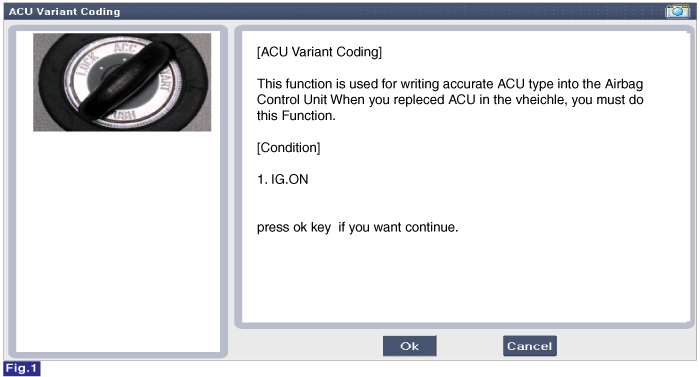
|
| (2) |
VIN Code entering screen 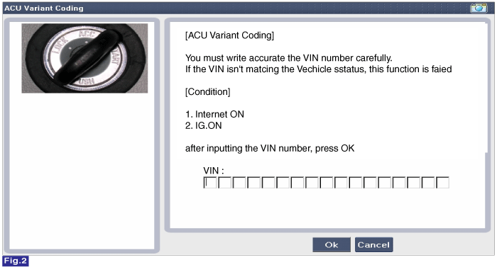
|
| (3) |
Variant Coding's proceeding screen-1 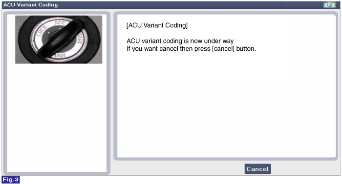
|
| (4) |
Variant Coding's proceeding screen-2 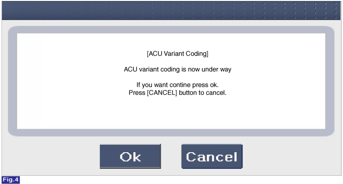
|
| (5) |
Variant Coding is completed 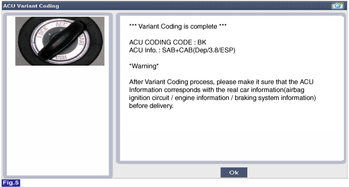
|
|
| 1. |
This screen is shown when you try variant coding on the SRSCM which has been performed before. 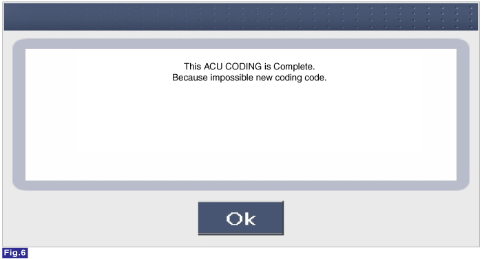
|
| 2. |
This screen is shown when communication failure has occurred. 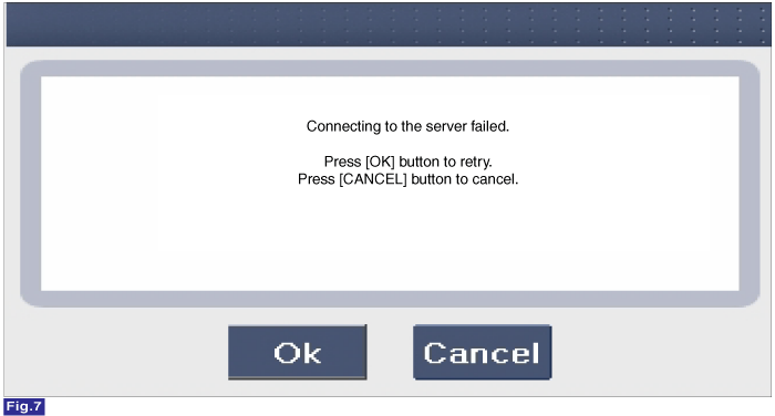
|
|
xnbsp; Off-line type on GDS (Use when not connected to the internet)
| 1. |
Turn the ignition switch OFF. |
| 3. |
Turn the ignition switch ON without the engine running. |
| 4. |
Select vehicle name and airbag system. |
| 5. |
Select variant coding mode. |
| 6. |
Follow the steps on the screen below.
| (1) |
Initial ACU Variant Coding screen 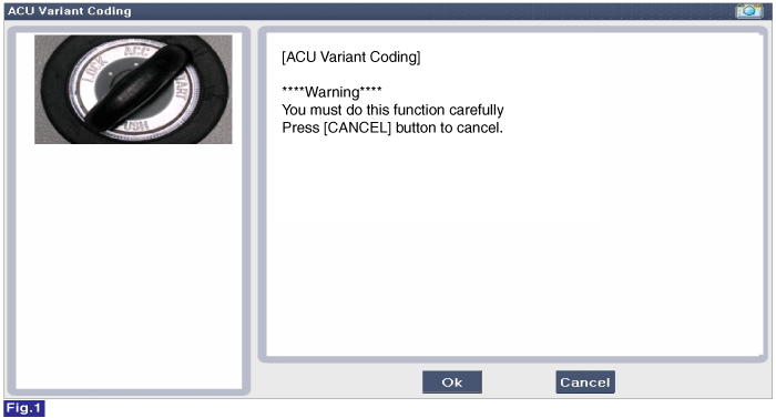
|
| (2) |
ACU Coding Code entering screen 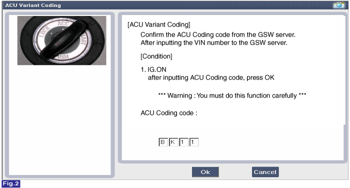
|
| (3) |
Rechecking ACU Coding Code entering screen 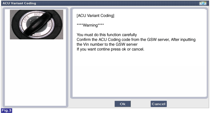
|
| (4) |
Variant Coding's proceeding screen-1 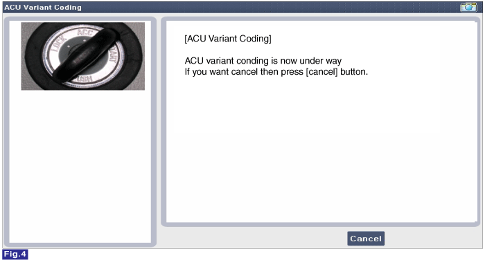
|
| (5) |
Variant Coding's proceeding screen-2 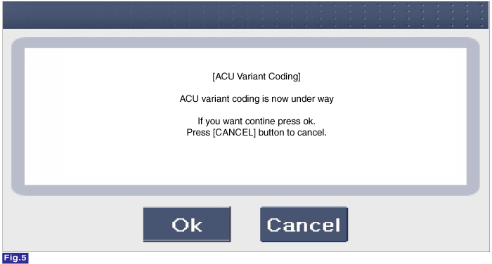
|
| (6) |
Variant Coding is completed 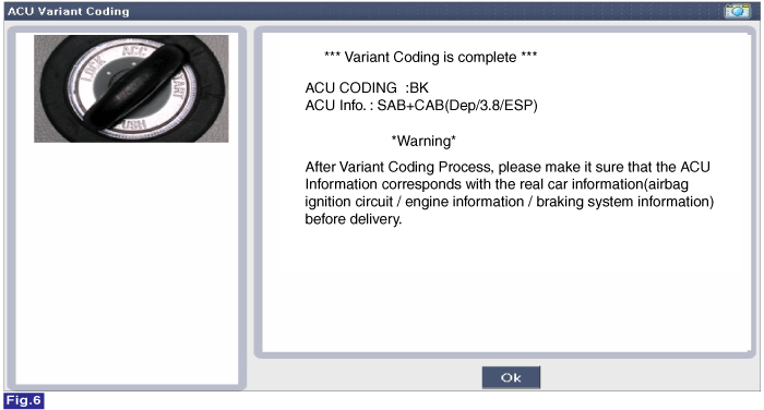
| 1. |
This screen is shown when you try variant coding on the SRSCM which has been performed before. 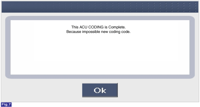
|
|
|
|
Description
The front impact sensor (FIS) is installed in the Front End
Module (FEM). They are remote sensors that detect acceleration due to a
collision at its mounting location. The primary p ...
See also:
Specifications
Specification
Ignition System
Ignition Coil
ItemSpecification Primary Coil Resistance (x)0.62 ± 10% [20°C (68°F)]Secondary Coil Resistance (kx)7.0 ± 15% [20°C (68°F)]
Spark Plug
ItemS ...
Auto Defogging Sensor Repair procedures
Inspection
To inspect and diagnose the sensor, refer to Self-Diagnosis procedure and DTC guide.
Replacement
1.
Disconnect the negative (-) battery terminal.
2.
Using a screwdriver or remov ...
Programming HomeLink®
✽ NOTICE
When programming a garage door opener, it is advised to park the vehicle
outside of the garage. • It is recommended that a new battery be placed in the
hand-held transmitter ...
 Hyundai Equus: SRS Control Module (SRSCM) Repair procedures
 Front Impact Sensor (FIS) Description and Operation


